
Pump Flow and Head Explained
Pump flow and head describe the required liquid delivery and the energy the pump must add. Keep both in the same duty statement and separate elevation, pressure and pipeline-loss contributions when reviewing the system.
The key decision
Write the duty as a paired flow and head condition. Separate elevation, pressure requirements and pipe losses, and retain the assumptions used to combine them.
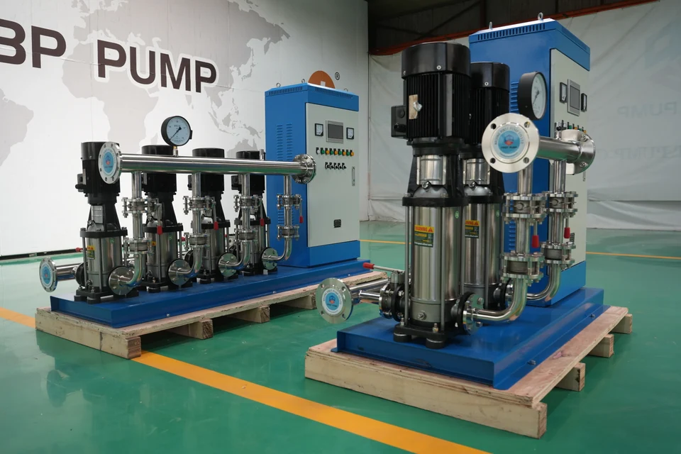
Supplied equipment photograph: vertical multistage pump sets. The complete package scope is confirmed per enquiry.
1. Keep pump flow and head together.
Flow is the quantity of liquid delivered per unit time, commonly recorded in m³/h or L/s. Head expresses energy per unit weight of liquid and is commonly recorded in metres. State both units on the duty sheet.
A pump curve relates head to flow for a particular configuration. Its highest head and highest flow should not be copied into one duty point. Request the proposed operating point and the associated model configuration.
| Incomplete statement | More useful record |
|---|---|
| “We need a 50 m pump.” | Required flow at 50 m head, plus liquid and operating conditions. |
| “The outlet must reach 4 bar.” | Required pressure at a defined location, inlet condition, flow and delivery route. |
| “Use the maximum flow.” | Normal, minimum and peak flow, with the corresponding system conditions. |
2. Separate the parts of the system requirement.
The system requirement may include elevation change, a pressure difference between source and destination, and losses through pipes, fittings and equipment. Keep these items separate in the calculation record. Do not add the same requirement twice.
The operating point occurs where the pump capability and system requirement meet. Changing a valve position, water level or operating arrangement can change that point. This is why the delivery route belongs with the pump enquiry.
3. Read a simple head breakdown.
Illustrative calculation record — not a BBP pump rating
| At the specified flow | Head contribution |
|---|---|
| Elevation difference | 12 m |
| Required pressure difference, expressed as head | 18 m |
| Calculated pipe and equipment losses | 25 m |
| Total for this stated condition | 55 m |
Here, 12 + 18 + 25 = 55 m. This example assumes the listed items fully describe the specified condition. It does not select a pump or establish inlet suitability.
For another flow, recheck the system losses. For another liquid, preserve the density basis used to convert pressure into head. Keep the original pressure values as well as the conversion.
4. Issue the duty with its assumptions.
Record the liquid, temperature, required flow and head, source and destination conditions, pipe route and operating pattern. Identify whether each value was measured, calculated or specified by the process designer.
If head has not been calculated, send the available site data and mark the calculation as open. Use the selection data checklist to gather the remaining inputs and pressure boosting guidance when the task is to increase delivery pressure.
Frequently asked questions
Are metres of head and bar interchangeable?
Converting between head and pressure requires the liquid density. Keep the density and pressure basis with the conversion.
Does a bigger pump always deliver more useful flow?
The result depends on the pump and system together. Compare the proposed curve with the system requirement and operating range.
Should I provide one duty point or a range?
Provide the normal point and any distinct minimum, peak or start-up conditions. Keep flow and head paired for each case.
Sources and further reading
General references used for this guide. Review the applicable model data and project requirements for your own duty.