1
Hot feedwater at the inlet
Assess suction margin at operating temperature. Coordinate tank level, suction losses and pump selection.
Address cavitation risk at its source.

BOILER FEED & HIGH-HEAD SOLUTIONS
Connect the delivery requirement, hot-water inlet and low-flow protection in one pumping approach.
Industrial steam · Process heating · High-head water service
Illustrative boiler-room scene
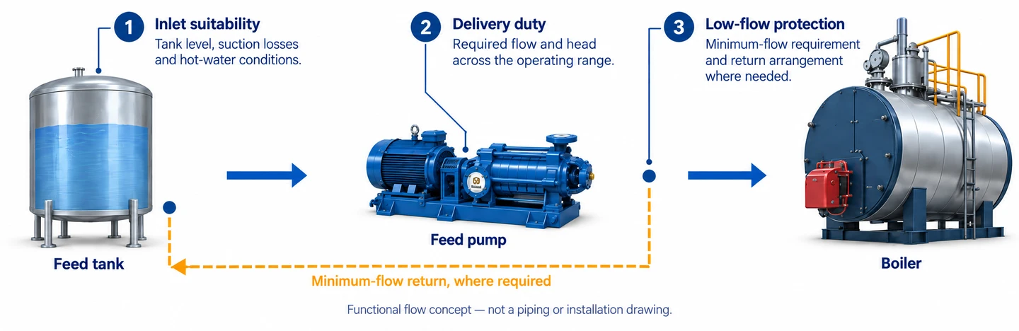
1
Assess suction margin at operating temperature. Coordinate tank level, suction losses and pump selection.
Address cavitation risk at its source.
2
Match the pump curve to the required flow and head across the agreed duty range, with a suitable control strategy.
Keep pump selection connected to boiler demand.
3
Define the minimum-flow requirement and a return arrangement where needed. Match the mechanical configuration to the thermal duty.
Account for operation beyond the normal duty point.
BEYOND THE DESIGN POINT
The pump must be reviewed for the conditions it will actually see, including periods when the boiler demand is low.
01 / START-UP
Record the feed-tank temperature and level at start-up. Check that the proposed filling, venting and start sequence suits the pump and the plant.
02 / NORMAL DUTY
Keep minimum, normal and maximum flow paired with their required delivery head. Review the proposed control method against these operating points.
03 / LOW DEMAND
Confirm the selected pump’s minimum-flow requirement and how it is maintained. Where a return is required, its route, control and supply scope must be defined.
EQUIPMENT FOR THE DUTY
A horizontal multistage assembly is the BBP product starting point for high-head water transfer and boiler-feed review. Match the selected version to the feedwater temperature, required head and available inlet conditions.
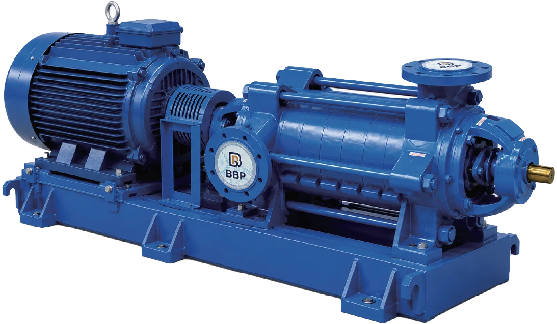
QD series brochure photograph
HYDRAULIC DUTY
Review the actual curve and stage selection for the required operating range.
THERMAL DUTY
Confirm the temperature limit, seal arrangement and wetted materials of the proposed model.
PLANT FIT
Check the assembly drawing, connections, base, drive and access around the horizontal set.
Comparing horizontal and vertical multistage arrangements?
THE COMPLETE FEEDWATER ARRANGEMENT
Keep the proposed equipment, control responsibilities and site provisions in the same enquiry.
Provide the pressure and level range, feedwater temperature, pump elevation and suction-line layout. These establish the inlet conditions for the pump review.
Provide the required flow, boiler or process pressure and the delivery route. Identify valves and other losses between the pump and the destination.
Agree the demand signal, start and stop sequence, standby strategy and low-flow provisions. Confirm the motor, control panel and instrument scope.
Request the selected curve, arrangement drawing, applicable operating instructions and agreed inspection documents for the proposed equipment.
Temperature suitability depends on the proposed series, version, materials and seal arrangement. Confirm the actual model limits and inlet conditions; a multistage construction alone does not establish hot-water suitability.
The multistage product page introduces the horizontal QD / QD(G) and vertical QDL / QDLS arrangements. Start the boiler-feed review with the applicable QD / QD(G) version and its specific curve, temperature limit and installation requirements.
Boiler pressure is one part of the duty. Required flow, delivery-route losses and the feedwater conditions at the inlet must be considered together.
The selected pump has an operating range that also applies when plant demand falls. A suitable minimum-flow provision, where required, addresses low-flow heating and related operating risks. Its arrangement and scope are defined for the plant.
Start with the operating problem and available system drawings.
Safe preview: this request is stored privately in WordPress. It does not send email or contact a CRM.