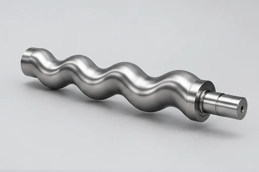
Screw rotor
An eccentric screw rotor advances the medium through sealed cavities.


Progressive Cavity Pump (Single-Screw)
A single-screw positive-displacement pump for viscous, particulate or fibrous media requiring stable flow and limited agitation.
Related resources: Chemical and petrochemical pump selection
models
Check model references against the original performance table, speed, materials and operating conditions.
| Model reference | Catalogue scope | Specifications | Enquiry |
|---|---|---|---|
| ALG20-1 | Original catalogue reference | Source PDF ↗ | |
| ALG20-2 | Original catalogue reference | Source PDF ↗ | |
| ALG25-1 | Original catalogue reference | Source PDF ↗ | |
| ALG25-2 | Original catalogue reference | Source PDF ↗ | |
| ALG30-1 | Original catalogue reference | Source PDF ↗ | |
| ALG30-2 | Original catalogue reference | Source PDF ↗ | |
| ALG35-1 | Original catalogue reference | Source PDF ↗ | |
| ALG35-2 | Original catalogue reference | Source PDF ↗ | |
| ALG40-1 | Original catalogue reference | Source PDF ↗ | |
| ALG40-2 | Original catalogue reference | Source PDF ↗ | |
| ALG50-1 | Original catalogue reference | Source PDF ↗ | |
| ALG50-2 | Original catalogue reference | Source PDF ↗ | |
| ALG60-1 | Original catalogue reference | Source PDF ↗ | |
| ALG60-2 | Original catalogue reference | Source PDF ↗ | |
| ALG70-1 | Original catalogue reference | Source PDF ↗ | |
| ALG70-2 | Original catalogue reference | Source PDF ↗ | |
| ALG85-1 | Original catalogue reference | Source PDF ↗ | |
| ALG85-2 | Original catalogue reference | Source PDF ↗ | |
| ALG105-1 | Original catalogue reference | Source PDF ↗ | |
| ALG105-2 | Original catalogue reference | Source PDF ↗ | |
| ALG135-1 | Original catalogue reference | Source PDF ↗ | |
| ALG135-2 | Original catalogue reference | Source PDF ↗ |
Use the original model table with its stated speed, impeller and units. A catalogue range does not guarantee a combined operating point.
overview
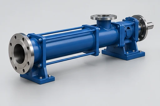
A progressing-cavity pump moves liquid through the rotor and stator. Viscosity, solids, temperature, speed and dry-running risk influence the selected materials and operating limits.
A single-screw positive-displacement pump for viscous, particulate or fibrous media requiring stable flow and limited agitation.
AI-generated family illustrations. The selected configuration follows the agreed model and drawing.
construction
An eccentric screw rotor advances the medium through sealed cavities.
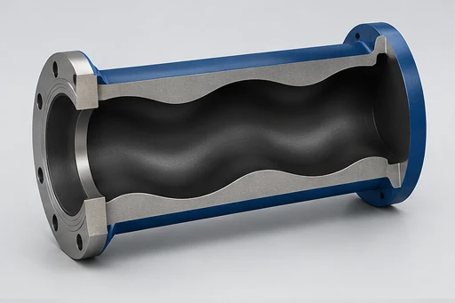
The fixed stator works with the rotor; compatibility and wear depend on the liquid, particles and temperature.
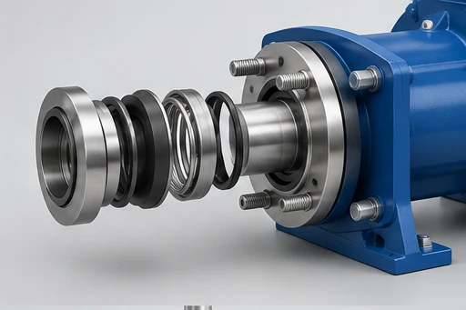
Define the seal against the actual liquid and the available operating and maintenance conditions.
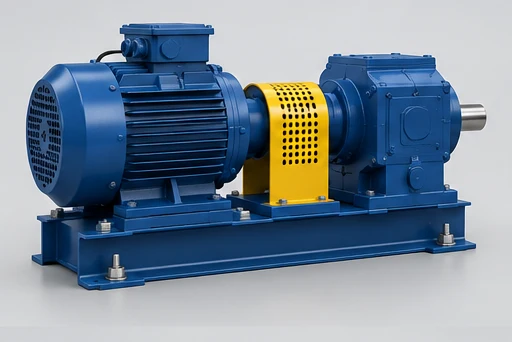
Check speed, pressure, viscosity and the catalogue limits together. Include the required speed-control method.
AI-generated family illustrations. The selected configuration follows the agreed model and drawing.
duty requirements
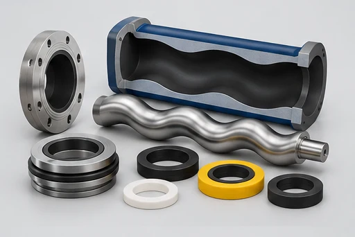
Review medium name and composition, required flow, required differential pressure, operating temperature, suction conditions, installation arrangement, power supply and drive method, materials, standards and inspection requirements, required supply scope, full chemical composition and concentration, density and viscosity, flammability, toxicity, crystallisation and volatility, design pressure and temperature, seal and flushing requirements, applicable process standard together with the liquid composition, temperature and installation. The values on a catalogue page are not a substitute for checking the selected model curve and approved arrangement.
| Wetted components | Rotor / stator pair matched to medium |
|---|---|
| Sealing | Confirm material and shaft-seal configuration |
| Liquid / design limits | Confirm liquid composition, temperature, particles and operating conditions |
| medium name and composition | Include this information in the duty review and model selection |
| required flow | Include this information in the duty review and model selection |
| required differential pressure | Include this information in the duty review and model selection |
| operating temperature | Include this information in the duty review and model selection |
| suction conditions | Include this information in the duty review and model selection |
| installation arrangement | Include this information in the duty review and model selection |
| power supply and drive method | Include this information in the duty review and model selection |
| materials, standards and inspection requirements | Include this information in the duty review and model selection |
| required supply scope | Include this information in the duty review and model selection |
| full chemical composition and concentration | Include this information in the duty review and model selection |
| density and viscosity | Include this information in the duty review and model selection |
| flammability, toxicity, crystallisation and volatility | Include this information in the duty review and model selection |
| design pressure and temperature | Include this information in the duty review and model selection |
| seal and flushing requirements | Include this information in the duty review and model selection |
| applicable process standard | Include this information in the duty review and model selection |
AI-generated family illustrations. The selected configuration follows the agreed model and drawing.
installation
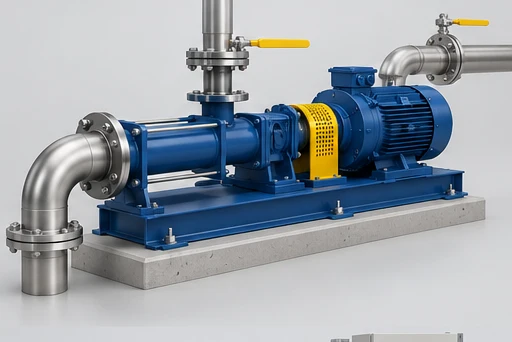
Match the rotor / stator pair to viscosity, solids, temperature and inlet conditions. Confirm dry-run protection and priming requirements.
Select speed against flow, differential pressure and the liquid. Confirm the gearbox / drive, supports and service access.
AI-generated family illustrations. The selected configuration follows the agreed model and drawing.
applications
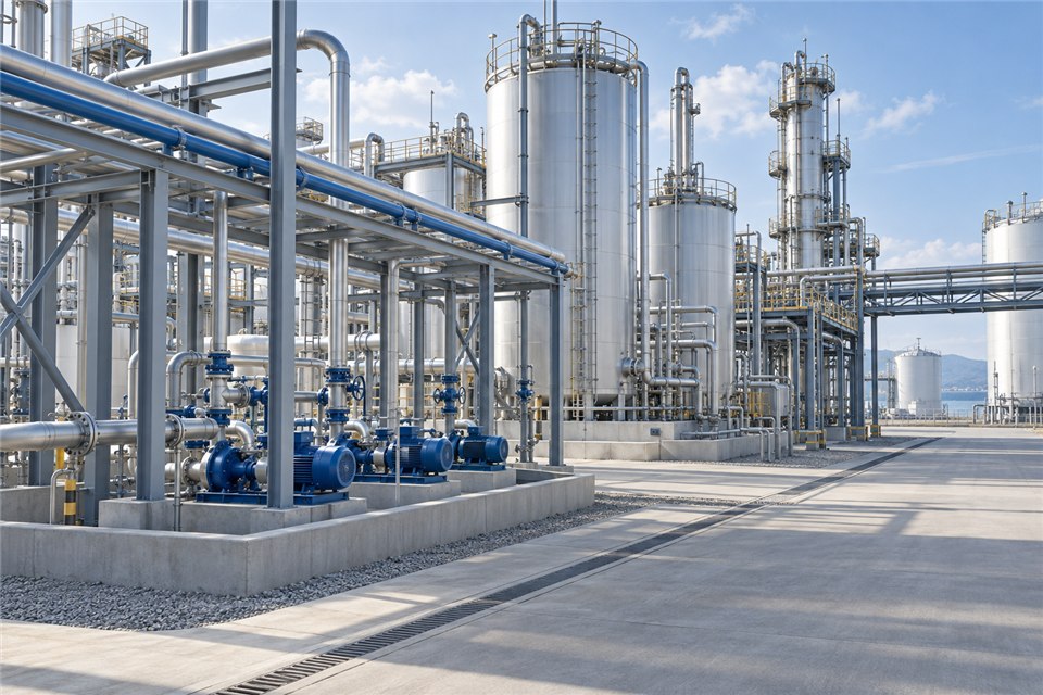
For environmental services, specify flow, differential pressure, viscosity, particles and stator compatibility. Check the proposed arrangement against horizontal progressing-cavity arrangement and rotor / stator pair matched to medium, then verify the operating point on the selected model curve.
For oil, confirm viscosity, temperature, suction conditions, seal plan and pressure envelope. Check the proposed arrangement against horizontal progressing-cavity arrangement and rotor / stator pair matched to medium, then verify the operating point on the selected model curve.
For food, specify flow, differential pressure, viscosity, particles and stator compatibility. Check the proposed arrangement against horizontal progressing-cavity arrangement and rotor / stator pair matched to medium, then verify the operating point on the selected model curve.
For papermaking, specify flow, differential pressure, viscosity, particles and stator compatibility. Check the proposed arrangement against horizontal progressing-cavity arrangement and rotor / stator pair matched to medium, then verify the operating point on the selected model curve.
For chemical processing, provide the complete composition, concentration, temperature and seal-utility requirements. Check the proposed arrangement against horizontal progressing-cavity arrangement and rotor / stator pair matched to medium, then verify the operating point on the selected model curve.
supply scope
Define the pump configuration, installation interfaces, controls and documents in the quotation.
Hydraulic end, materials, sealing and interfaces for your driver or installation.
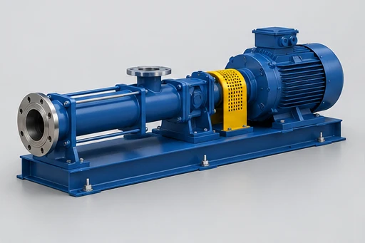
Pump and matched motor, coupling / transmission, base and guarding as applicable.
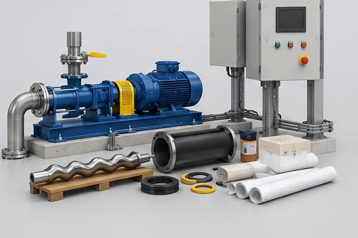
Agreed supports, controls, auxiliaries, spares and technical documents.
AI-generated family illustrations. The selected configuration follows the agreed model and drawing.
manufacturing
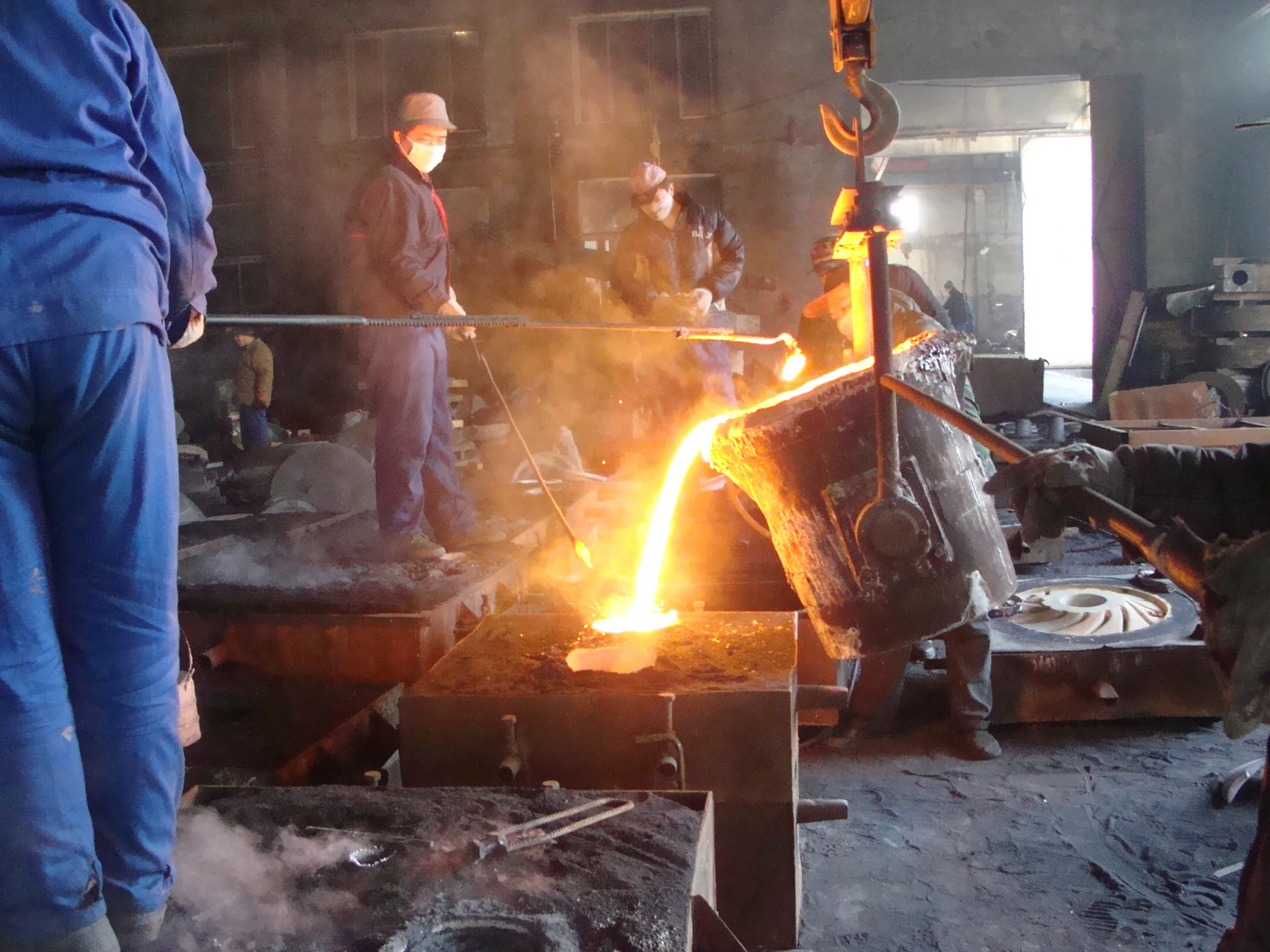
Casting produces pump components to the construction and material requirements of the selected equipment. The applicable alloy, pattern and component geometry depend on the pump family and the agreed operating conditions.
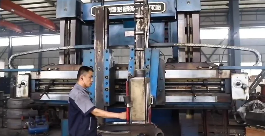
Machining prepares mounting faces, bores, fits and connection interfaces for assembly. OEM parts should be reviewed against the approved drawing and revision, including the dimensions that determine interchange and installation.
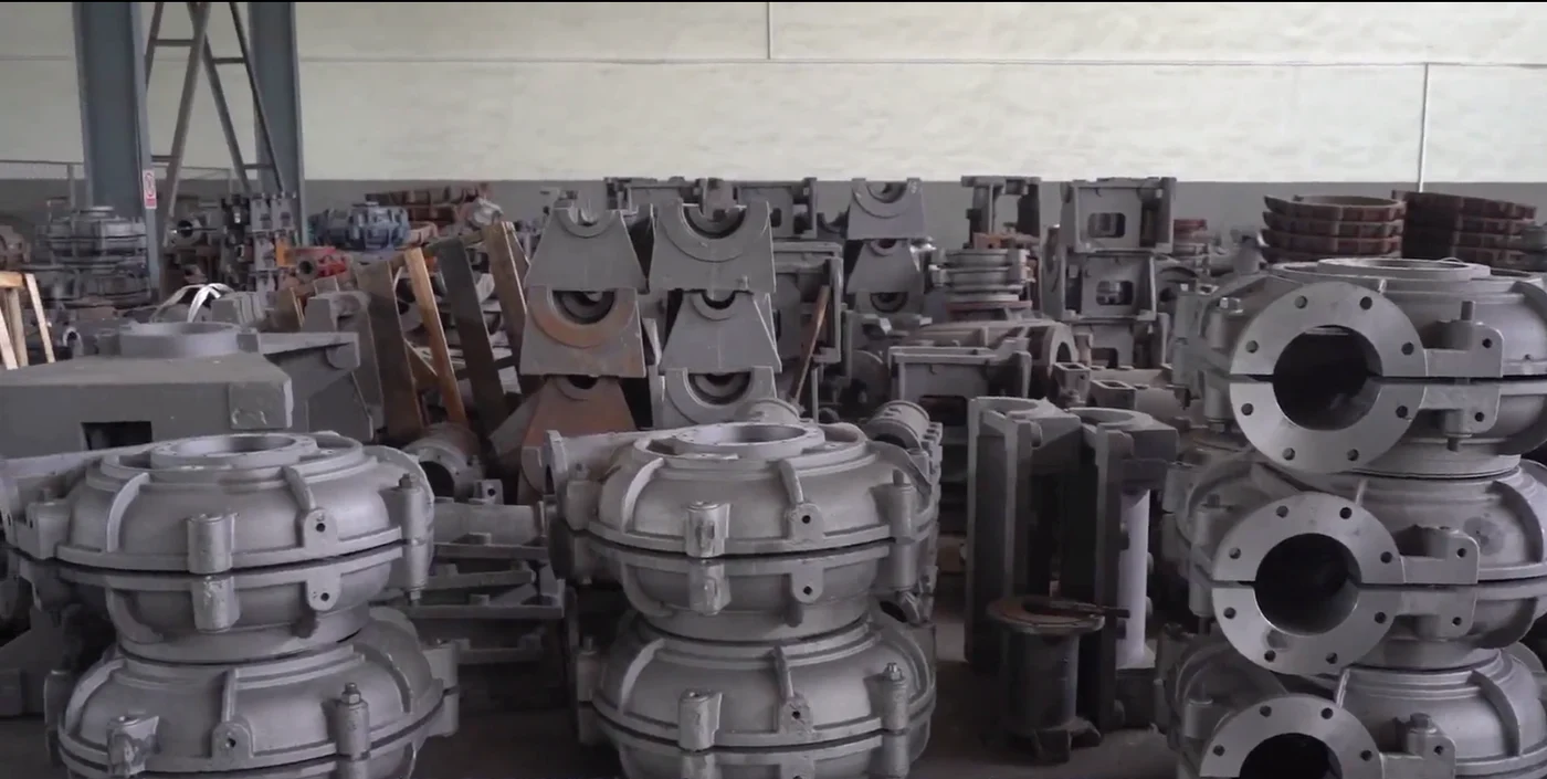
Owner-supplied factory photograph showing pump castings staged in a work area. The exact parts and process route depend on the selected order.
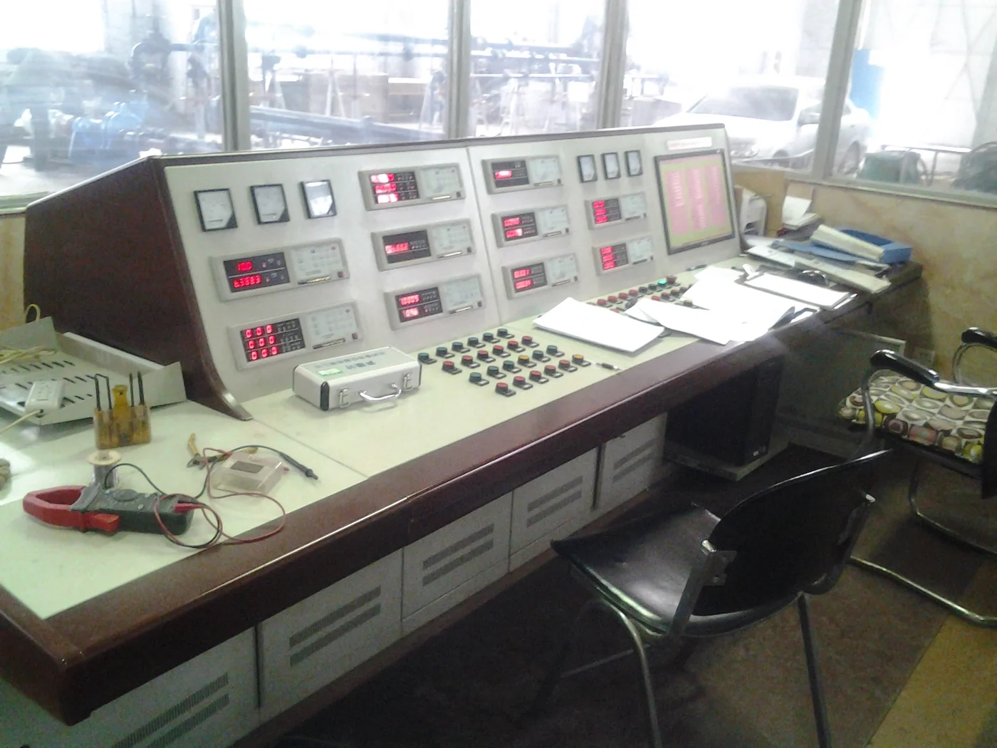
Owner-supplied factory photograph showing test-control equipment. The inspection points and acceptance records must be agreed for the selected equipment.
documents
Original series manual and technical references. Review the applicable model, version and units.
Open original PDF View family brochure ↗Request the selected model curve, arrangement drawing, materials, installation instructions and agreed inspection records.
Request technical documentsquestions
medium name and composition; required flow; required differential pressure; operating temperature; suction conditions; installation arrangement; power supply and drive method; materials, standards and inspection requirements; required supply scope; full chemical composition and concentration; density and viscosity; flammability, toxicity, crystallisation and volatility; design pressure and temperature; seal and flushing requirements; applicable process standard. Review the complete duty on the applicable model curve.
Rotor / stator pair matched to medium. Confirm material and shaft-seal configuration. Confirm compatibility with the complete liquid composition and temperature.
Catalogue ranges summarize printed records and may combine different conditions. Check each model against its source curve and required speed.
Confirm pump, driver, controls, auxiliaries, spares, drawings, manuals and required test records in the agreed quotation.
enquiry
Describe the liquid, required output and site arrangement so BBP can review the model and equipment scope.