Home

SLURRY HANDLING

Metal Vertical Sump Slurry Pump

A metal wet end for abrasive sump duties.

A vertical sump pump with metal wet-end construction for abrasive slurry collected in pits and sumps.

Installation
Vertical sump, motor above liquid
Wet end
Wear-resistant metal construction; exact component grades are agreed for the duty.
Drive
Motor above the liquid
Selection
Duty, slurry & applicable curve

Compare catalogue operating records

Catalogue operating records

6 records

Range screening only. Flow/head limits are not interchangeable operating points. Open the printed table and request the applicable curve.

Catalogue modelOutlet mmFlow m³/hHead mSpeed rpmSource / selection
40C-BP407.2–184.3–5.51000PDF p. 7 ↗
40C-BP4010.08–24.848.7–10.91400PDF p. 7 ↗
40C-BP4016.2–39.621.4–27.42200PDF p. 7 ↗
65D-BP6519.08–48.65–6.7700PDF p. 8 ↗
65D-BP6526.28–65.889.8–12.8960PDF p. 8 ↗
65D-BP6540.32–102.623.5–30.81500PDF p. 8 ↗

40C-BP

Outlet 40 mm

Flow m³/h
7.2–18
Head m
4.3–5.5
Speed rpm
1000
PDF p. 7 ↗

40C-BP

Outlet 40 mm

Flow m³/h
10.08–24.84
Head m
8.7–10.9
Speed rpm
1400
PDF p. 7 ↗

40C-BP

Outlet 40 mm

Flow m³/h
16.2–39.6
Head m
21.4–27.4
Speed rpm
2200
PDF p. 7 ↗

65D-BP

Outlet 65 mm

Flow m³/h
19.08–48.6
Head m
5–6.7
Speed rpm
700
PDF p. 8 ↗

65D-BP

Outlet 65 mm

Flow m³/h
26.28–65.88
Head m
9.8–12.8
Speed rpm
960
PDF p. 8 ↗

65D-BP

Outlet 65 mm

Flow m³/h
40.32–102.6
Head m
23.5–30.8
Speed rpm
1500
PDF p. 8 ↗

Six example BP metal-pump speed records from physical PDF pages 7–8. Each range summarizes three printed operating points. More BP sizes are available in the source catalogue; none of these points is relabelled as BPR.

Need a model-specific curve?

Provide the actual slurry and operating point so the proposed model, speed and material can be reviewed together.

Metal Vertical Sump Slurry Pump construction and operation

The metal vertical sump pump works with its hydraulic end immersed in the sump and its drive above the liquid. The catalogue describes this arrangement for abrasive, dense slurry collected in mineral-processing, coal-preparation and other industrial pits.

The standard arrangement and extension-shaft arrangements require different installation reviews. The manual identifies guide-bearing flushing for extension versions. Establish the required immersion length, liquid levels and utility provision from the applicable drawing, then select the operating point from the metal-pump performance table.

  • Metal hydraulic componentsReview impeller, casing, back liner and discharge-pipe materials around the abrasive duty.
  • Sump-mounted constructionMounting plate, shaft length and minimum liquid level define the installation geometry.
  • Extension arrangement reviewGuide bearings and their flushing provision must follow the documented extension design.

Components, materials and seals

Vertical sump-pump wet-end components

Impeller & casing

The hydraulic end operates below the mounting level. Match its material to abrasion and liquid chemistry.

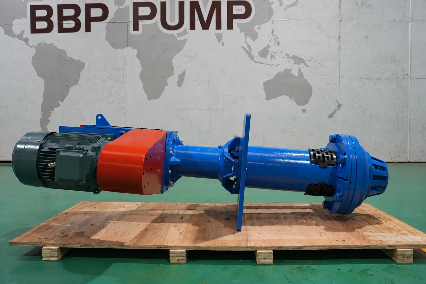
Illustration of a vertical sump slurry pump laid horizontally on a pallet with its motor attached

Shaft & column

Column and shaft length follow the sump geometry and operating liquid levels. Extension designs require their own review.

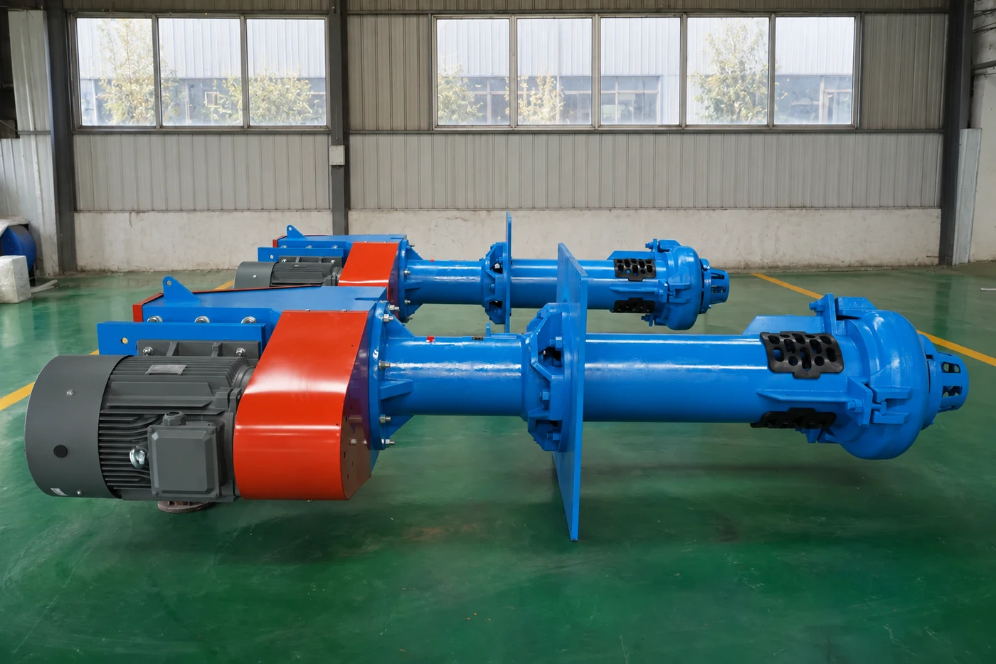
BP vertical sump pump photographed in the workshop

Bearing support

Keep the above-liquid drive and bearing support accessible for lubrication, inspection and removal.

Illustration of pair of vertical sump slurry pumps

Discharge & installation

Support the discharge pipe independently and agree the outlet interface, lifting path and removal clearance.

Materials, sealing & duty requirements

Review itemRequired information
Wetted componentsWear-resistant metal construction; exact component grades are agreed for the duty.
Sealing / interfacesSump arrangement; confirm shaft details
Solids informationConcentration basis, particle distribution, maximum size, hardness and shape
Liquid conditionsComplete chemistry, liquid and solids densities, operating temperature
Installation informationSump dimensions, liquid levels, immersion and mounting plate
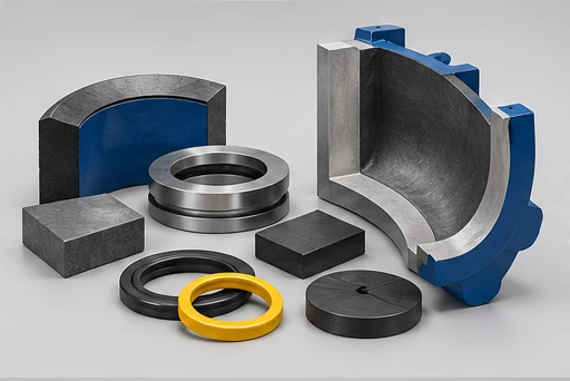
Metal Vertical Sump Slurry Pump: illustrative wear materials and shaft-seal components

Check the complete operating point

  • Normal and maximum flow / head
  • Density and concentration range
  • Particles, chemistry and temperature
  • Site arrangement and operating cycle

AI-generated family illustrations. The selected configuration follows the agreed model and drawing.

Installation & drive arrangement

Vertical sump-pump wet-end components

Mounting plate & immersion

Coordinate the mounting level, shaft length, normal and minimum liquid levels, and pump removal path.

Illustration of pair of vertical sump slurry pumps

Above-liquid motor arrangement

Review the selected drive speed, alignment and access around the motor support. Extension-shaft flushing follows the documented design.

  • Mounting elevation
  • Liquid-level range
  • Removal clearance
  • Discharge support

Typical applications

Application descriptions are selection contexts. Suitability depends on the selected equipment and actual process conditions.

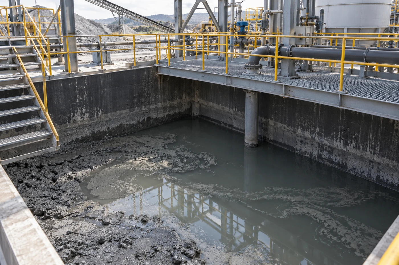
AI-generated industrial sump application scene

Mineral-process sumps

Include the accumulation of solids and the available sump volume in the duty review.

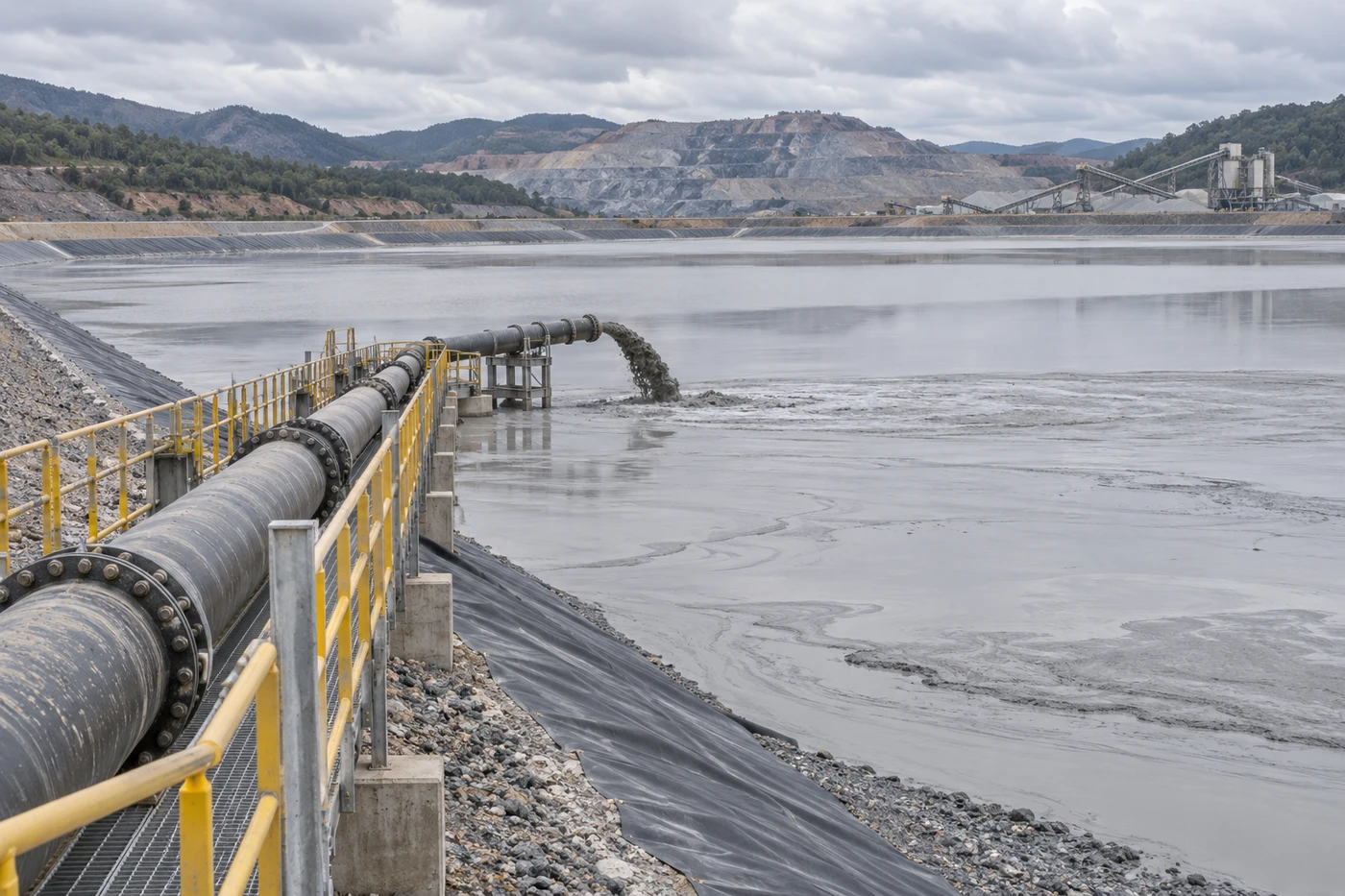
AI illustration of a tailings pipeline discharging slurry into a storage pond

Tailings collection

State concentration fluctuations and whether the inlet area can collect coarse settled material.

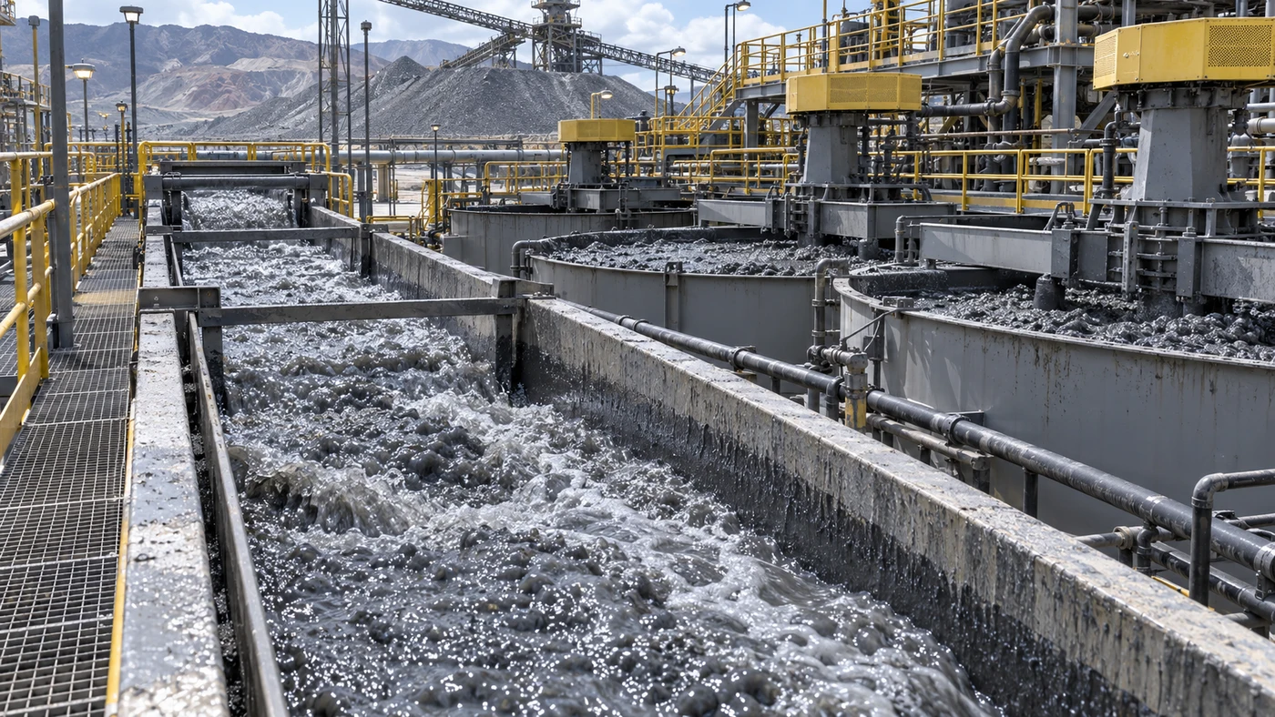
AI illustration of mineral-processing channels carrying slurry through an industrial plant

Coal preparation pits

Provide liquid chemistry, grading and the operating liquid-level range.

Choose the supply scope

Select a scope below to carry it into the enquiry. The final equipment and documents are defined in the quotation.

Illustration of a vertical sump slurry pump laid horizontally on a pallet with its motor attached

Pump assembly

Wet end, shaft, column and mounting components for the agreed immersion.

  • Hydraulic end and material
  • Immersion and plate details
  • Discharge interface
Vertical sump-pump wet-end components

Motor-driven assembly

Pump and above-liquid motor with the agreed transmission and supports.

  • Motor and selected speed
  • Support and guarding
  • Alignment requirements
Illustration of pair of vertical sump slurry pumps

Installation & spares

Agree site interfaces, extension services, wear parts and documents.

  • Mounting and lifting
  • Extension flushing if applicable
  • Spares and drawings

Define what arrives with the equipment

Equipment & interfaces

Selected pump, materials, seal, drive, connections, mounting and any required auxiliary services.

Inspection & documentation

Agree drawing revision, inspection requirements, applicable acceptance criteria and the documents required with delivery.

Packing & service spares

Specify preservation, packing, identification and an initial spare-parts list appropriate to the maintenance plan.

From preparation to shipment

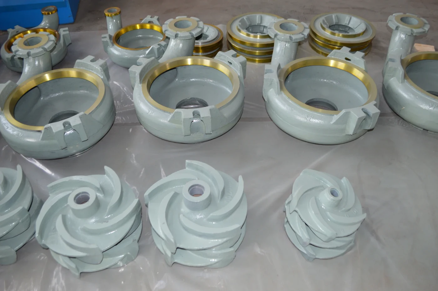
Slurry pump casings, impellers and mounting components arranged on the workshop floor

Components & material review

Identify component drawings and materials for the agreed pump or parts scope.

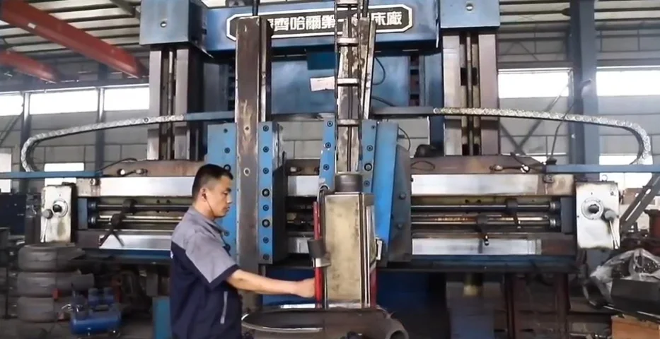
Operator working at a large machining machine in the workshop

Machining & interfaces

Check the critical faces, bores, fits and connections against the applicable drawing.

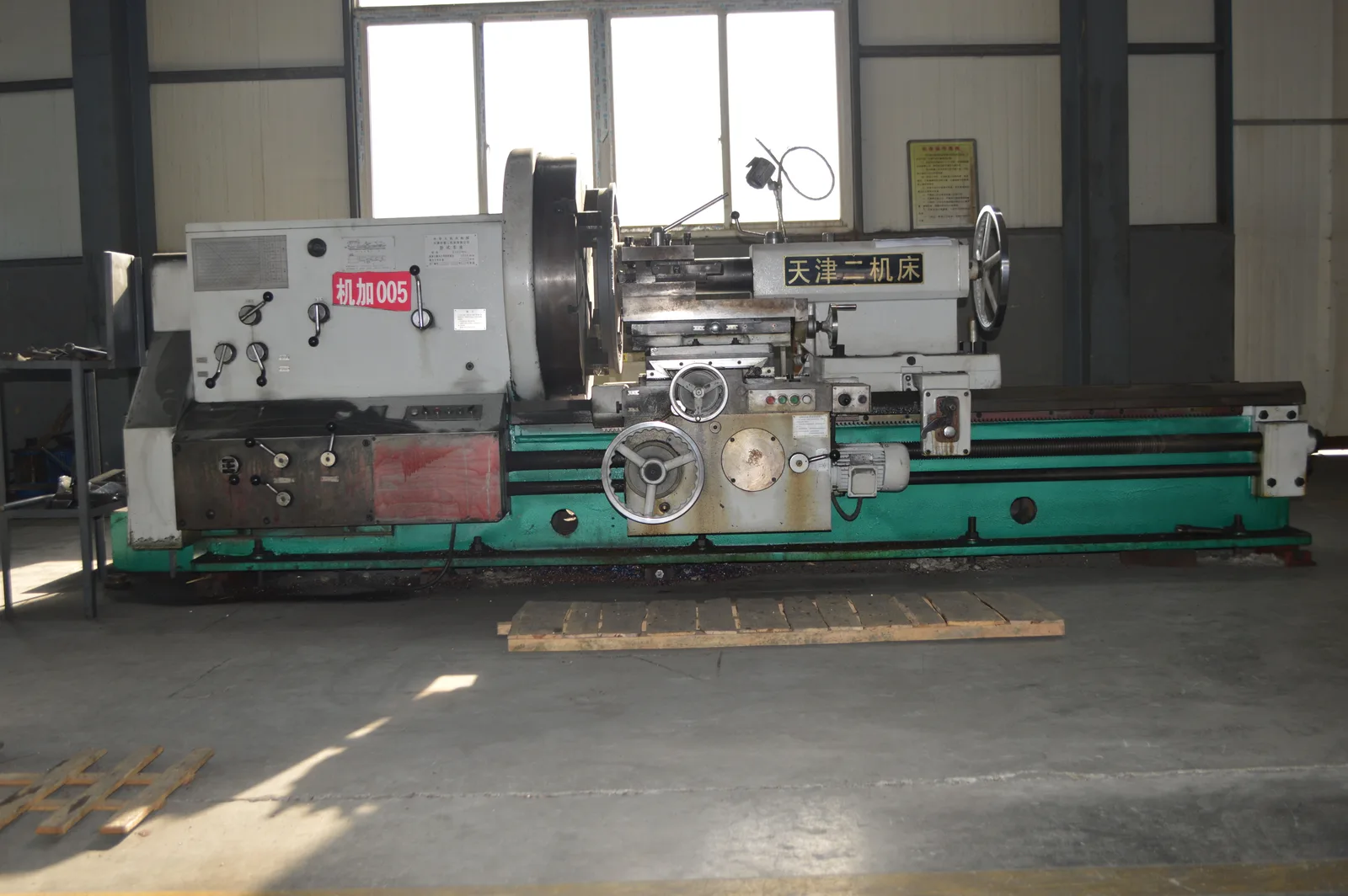
Industrial lathe for machining pump components

Inspection planning

Agree inspection points, acceptance criteria and any requested records before supply.

Pump assemblies prepared in the workshop

Packing & handover

Confirm identification, preservation, packing and the documents required for handover.

Technical documents

BP vertical sump pump photographed in the workshop

Original source catalogue

Original series introduction, drawings and available technical tables.

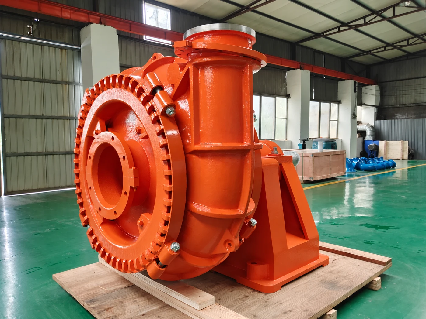
Illustration of an orange gravel pump with a large inlet flange and discharge outlet

Slurry family brochure

Product arrangements and original family drawings. Confirm the applicable series and model.

Illustration of a vertical sump slurry pump laid horizontally on a pallet with its motor attached

Selected curve & arrangement

Request the applicable curve, materials, dimensions and installation instructions.

Pump questions

Does an extended shaft need additional services?
The manual identifies guide bearings and flushing for extension-shaft arrangements. Agree the extension design, flush-liquid quality, supply conditions and installation instructions before ordering.
How is the pump selected?
Start with flow, total dynamic head, slurry density, solids concentration and size, temperature, chemistry and installation. Review these together on the applicable curve.
Are the images dimensional drawings?
Catalogue drawings show the source construction. Family exterior references and illustrative components are labelled. Use the selected model’s approved arrangement drawing for dimensions and installation.
What is included in the quotation?
The selected supply scope, materials, interfaces, inspection requirements, spares and documents must be agreed in the quotation. An illustration alone does not define the delivered equipment.
What if there is no numerical table on this page?
Send the operating requirement for a model-specific curve review. A product introduction or family envelope cannot replace a selected pump curve.
How do I use this enquiry form?
Choose any model, installation and supply options above, complete the required fields, and prepare a draft. Review it before copying, downloading or opening it in your email application.

Tell us about your slurry duty

Share the liquid, operating point and site arrangement for a useful selection discussion.

  • Operating pointFlow, head and operating range.
  • SlurryDensity, concentration and particles.
  • InstallationLiquid levels, drive and utilities.
Please enter your name.
Please enter your requirements.
0/5000
Please confirm that we may respond to your enquiry.