Home
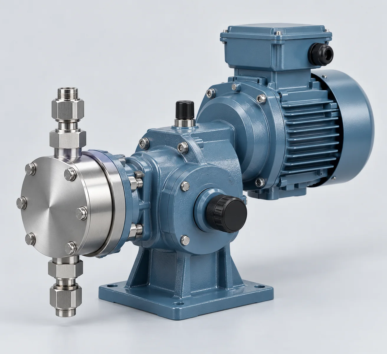
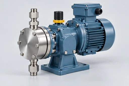
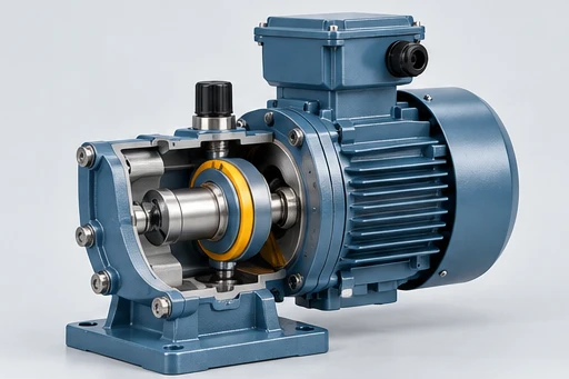
Mechanical Diaphragm Metering Pump product-family illustration showing a typical pump arrangement
AI-generated family illustration — not a product photograph.

Mechanical Diaphragm Metering Pump

Mechanical Diaphragm Metering Pump

Continuous process dosing.

Motor-driven mechanical diaphragm delivery for controlled chemical injection. Confirm motor speed, stroke adjustment and the relationship between capacity and injection pressure. Define the chemical, required dosing rate and discharge pressure before selecting the liquid end.

Installation
Chemical tank, suction line and injection point reviewed as a dosing system
Wet end
Liquid-end materials, diaphragm and valve parts selected for the chemical
Sealing
Diaphragm separation with selected inlet and discharge valve materials
Drive
Motor, gearbox and eccentric mechanism
View public product reference ↗

Configuration review

Mechanical Diaphragm Metering Pump selection requirements

Specify the operating requirement before selecting a model.

Define the selected configuration

Motor-driven mechanical diaphragm delivery for controlled chemical injection. Confirm motor speed, stroke adjustment and the relationship between capacity and injection pressure. Define the chemical, required dosing rate and discharge pressure before selecting the liquid end.

  • Chemical composition, concentration and temperature
  • Minimum, normal and maximum dosing rate
  • Injection pressure and its operating variation
  • Tank level, suction line and gas-release tendency
  • Control signals, calibration and supply scope
Request model-specific data

Request a hydraulic curve, arrangement drawing, wetted-material schedule and operating instructions for the proposed configuration. Broad public ranges do not establish a combined duty point.

Request a selection review

overview

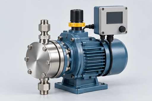
Mechanical Diaphragm Metering Pump construction and operation

Mechanical Diaphragm Metering Pump: illustrative pump assembly and construction

Motor-driven mechanical diaphragm

The impeller transfers energy to the liquid through the pump casing. Final selection depends on the model curve, liquid properties, sealing arrangement, drive and piping conditions.

Motor-driven mechanical diaphragm delivery for controlled chemical injection. Confirm motor speed, stroke adjustment and the relationship between capacity and injection pressure. Define the chemical, required dosing rate and discharge pressure before selecting the liquid end.

  • Motor, gearbox and eccentric mechanism
  • Confirm motor speed, stroke adjustment and the relationship between capacity and injection pressure.
  • Metering head with inlet and outlet check valves; assess gas release and loss of prime

AI-generated family illustrations. The selected configuration follows the agreed model and drawing.

construction

Components, materials and seals

Diaphragm & liquid end concept for Mechanical Diaphragm Metering Pump

Diaphragm & liquid end

Review chemical composition, diaphragm compatibility and the separation between the chemical and actuator.

Motor, gearbox and eccentric mechanism concept for Mechanical Diaphragm Metering Pump

Motor, gearbox and eccentric mechanism

Confirm motor speed, stroke adjustment and the relationship between capacity and injection pressure.

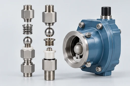
Inlet & discharge valves concept for Mechanical Diaphragm Metering Pump

Inlet & discharge valves

Assess gas release, solids, suction conditions and valve materials. Include cleaning and service access.

Control & calibration concept for Mechanical Diaphragm Metering Pump

Control & calibration

Agree the dosing range, manual or external control, calibration method and required records.

AI-generated family illustrations. The selected configuration follows the agreed model and drawing.

duty requirements

Materials, sealing & duty requirements

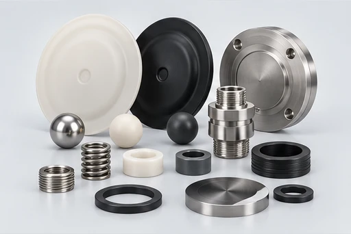
Mechanical Diaphragm Metering Pump: illustrative wetted materials and sealing components

Review chemical composition, concentration and temperature, minimum, normal and maximum dosing rate, injection pressure and its operating variation, tank level, suction line and gas-release tendency, control signals, calibration and supply scope together with the liquid composition, temperature and installation. The values on a catalogue page are not a substitute for checking the selected model curve and approved arrangement.

Wetted componentsLiquid-end materials, diaphragm and valve parts selected for the chemical
SealingDiaphragm separation with selected inlet and discharge valve materials
Liquid / design limitsConfirm liquid composition, temperature, particles and operating conditions
Chemical composition, concentration and temperatureInclude this information in the duty review and model selection
Minimum, normal and maximum dosing rateInclude this information in the duty review and model selection
Injection pressure and its operating variationInclude this information in the duty review and model selection
Tank level, suction line and gas-release tendencyInclude this information in the duty review and model selection
Control signals, calibration and supply scopeInclude this information in the duty review and model selection

AI-generated family illustrations. The selected configuration follows the agreed model and drawing.

installation

Installation & drive arrangement

Mechanical Diaphragm Metering Pump: illustrative installation and drive arrangement

Suction & injection

Provide tank levels, suction-line layout and the injection pressure. Define isolation, back-pressure and pressure-relief arrangements for the actual system.

Control & calibration

Confirm input signals, start/stop logic, low-level protection and calibration access. Review delivery across the intended operating range.

Before installation

  • Foundation / mounting and pipe supports
  • Liquid supply and discharge connections
  • Electrical supply and maintenance access
Discuss the installation

AI-generated family illustrations. The selected configuration follows the agreed model and drawing.

applications

Typical applications

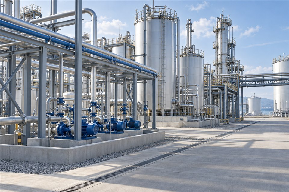
Application illustration: chemical process-liquid transfer

Cooling-water chemical dosing

For cooling-water chemical dosing, define the injection point, liquid compatibility and control signal. Check the proposed arrangement against chemical tank, suction line and injection point reviewed as a dosing system and liquid-end materials, diaphragm and valve parts selected for the chemical, then verify the operating point on the selected model curve.

Water-treatment dosing

For water-treatment dosing, define the injection point, liquid compatibility and control signal. Check the proposed arrangement against chemical tank, suction line and injection point reviewed as a dosing system and liquid-end materials, diaphragm and valve parts selected for the chemical, then verify the operating point on the selected model curve.

Controlled chemical feed

For controlled chemical feed, state the dosing range, injection pressure, chemical concentration and suction supply. Check the proposed arrangement against chemical tank, suction line and injection point reviewed as a dosing system and liquid-end materials, diaphragm and valve parts selected for the chemical, then verify the operating point on the selected model curve.

supply scope

Choose the supply scope for this pump

Define the pump configuration, installation interfaces, controls and documents in the quotation.

Metering pump illustration for Mechanical Diaphragm Metering Pump

Metering pump

Selected liquid end, actuator or tube, drive and local adjustment.

Chemical-feed equipment illustration for Mechanical Diaphragm Metering Pump

Chemical-feed equipment

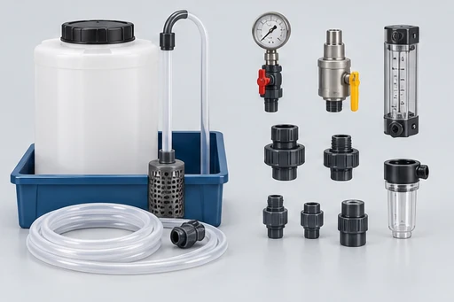
Specified valves, suction and injection fittings, calibration equipment and containment.

Control integration illustration for Mechanical Diaphragm Metering Pump

Control integration

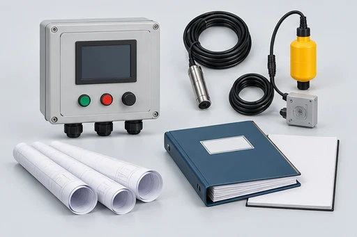
Agreed process signals, protection, manuals, calibration procedure and equipment schedule.

AI-generated family illustrations. The selected configuration follows the agreed model and drawing.

manufacturing

From preparation to shipment

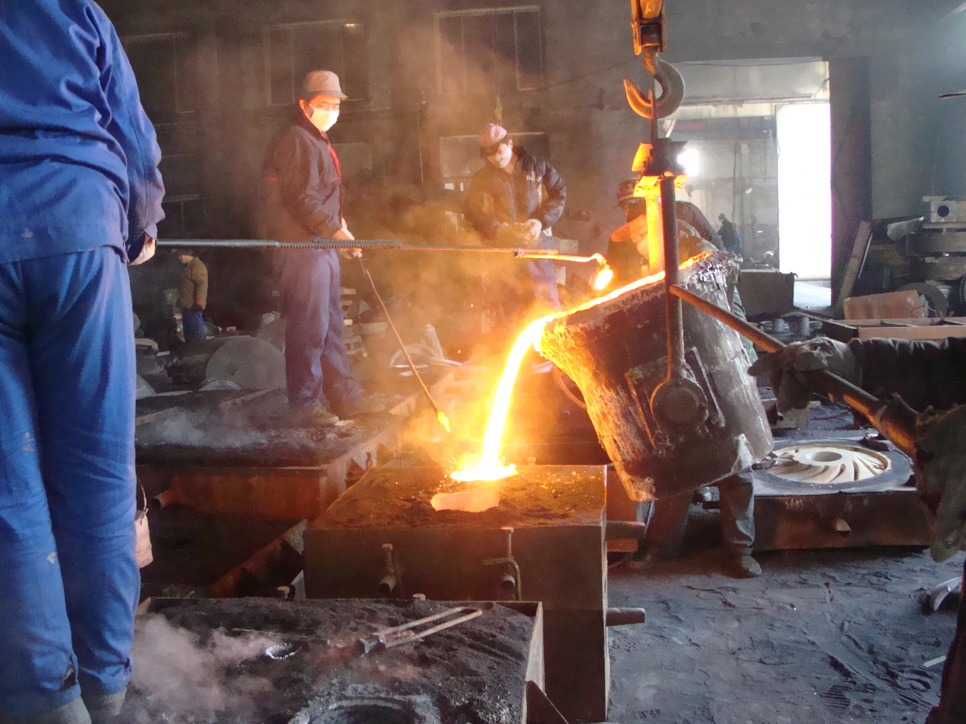
Foundry workers pouring molten metal into a pump-component mold

Casting of pump components

Casting produces pump components to the construction and material requirements of the selected equipment. The applicable alloy, pattern and component geometry depend on the pump family and the agreed operating conditions.

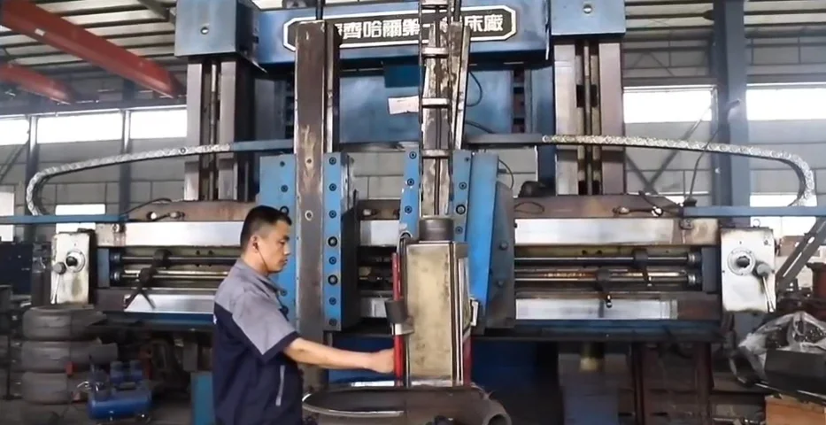
Operator working at a large machining machine in the workshop

Finish machining

Machining prepares mounting faces, bores, fits and connection interfaces for assembly. OEM parts should be reviewed against the approved drawing and revision, including the dimensions that determine interchange and installation.

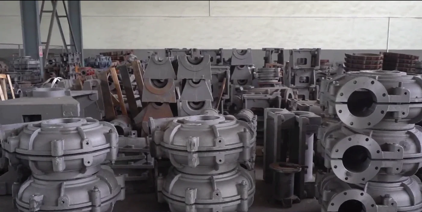
Pump castings staged for manufacturing

Component handling & staging

Owner-supplied factory photograph showing pump castings staged in a work area. The exact parts and process route depend on the selected order.

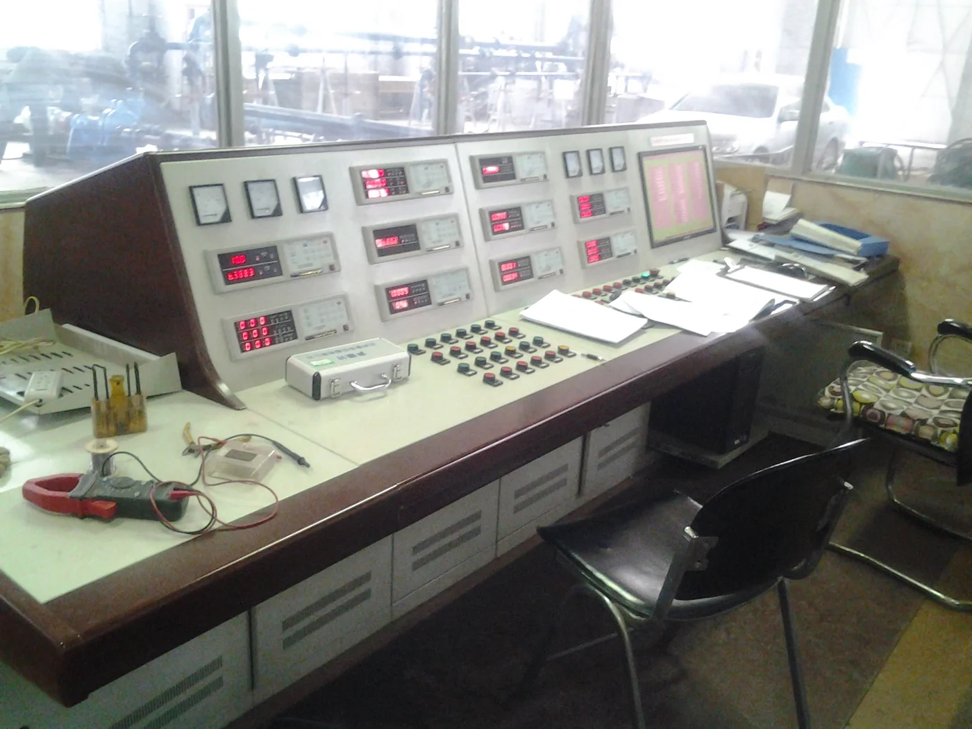
Factory test-control equipment

Inspection equipment & controls

Owner-supplied factory photograph showing test-control equipment. The inspection points and acceptance records must be agreed for the selected equipment.

View manufacturing

Technical references

Technical documents

Public product reference

The owner-selected reference identifies the product direction. Ratings, material availability and approvals must be confirmed for the quoted equipment.

View product reference

Model-specific curves & drawings

Request the selected performance curve, installation drawing, material schedule, operating manual and agreed inspection records.

Request technical documents

questions

Mechanical Diaphragm Metering Pump FAQs

What information is needed for selection?

Chemical composition, concentration and temperature; Minimum, normal and maximum dosing rate; Injection pressure and its operating variation; Tank level, suction line and gas-release tendency; Control signals, calibration and supply scope.

Which materials and sealing can be supplied?

Liquid-end materials, diaphragm and valve parts selected for the chemical. Diaphragm separation with selected inlet and discharge valve materials. Confirm compatibility with the complete liquid composition and temperature.

Are public ranges a selected model duty?

The public reference describes this product direction. Request a model-specific curve, arrangement drawing and material schedule; public range and certification statements are not model approval.

What is included in the delivery?

Confirm pump, driver, controls, auxiliaries, spares, drawings, manuals and required test records in the agreed quotation.

enquiry

Tell us about your pump duty

Describe the liquid, required output and site arrangement so BBP can review the model and equipment scope.

  • Chemical composition, concentration and temperature
  • Minimum, normal and maximum dosing rate
  • Injection pressure and its operating variation
  • Tank level, suction line and gas-release tendency
  • Control signals, calibration and supply scope
contact@bbpmfg.com
+86 182 1085 0516

Please enter your name.
Please enter your requirements.
0/5000
Please confirm that we may respond to your enquiry.