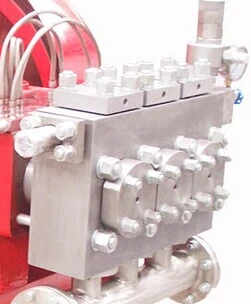
Fluid end & valve access
The photographed pump head brings the delivery valves and liquid connections together. Select its material and service access for the liquid and pressure duty.


Triplex Plunger Pump
The 3DP triplex plunger pump uses three plungers for high-pressure cleaning, descaling, pressure testing and water injection. Review the available model data and provide the required flow, discharge pressure, liquid properties and operating schedule for configuration review.
Related resources: High-pressure plunger pump applications
models
Check model references against the original performance table, speed, materials and operating conditions.
| Model reference | Catalogue scope | Specifications | Enquiry |
|---|---|---|---|
| 3DP80 | Original catalogue reference | Source PDF ↗ | |
| 3DP40 | Original catalogue reference | Source PDF ↗ | |
| 3DP60 | Original catalogue reference | Source PDF ↗ | |
| 3DP20 | Original catalogue reference | Source PDF ↗ | |
| 3DP35 | Original catalogue reference | Source PDF ↗ |
The catalogue contains 3DP and 3ZH entries. Only the original 3DP model references are listed here; photographs show supplied arrangements, not a verified model-to-photo mapping.
overview

The crank-driven power end converts rotary motion into three reciprocating plunger strokes. The fluid end admits and discharges liquid through valves, while the drive, packing and pressure-control equipment must suit the working liquid and operating cycle.
Triplex reciprocating pumps for industrial high-pressure cleaning, descaling, pressure testing and water injection.
construction
The photographed pump head brings the delivery valves and liquid connections together. Select its material and service access for the liquid and pressure duty.
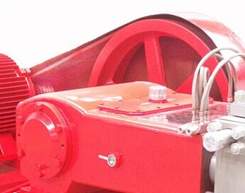
The motor and guarded transmission drive the crankcase. Confirm the required pump speed, belt or coupling arrangement, lubrication and maintenance clearance.

The photographed electric arrangement mounts the pump and motor together. Review alignment, mounting loads and access before finalising the installation.

The gauge and pulsation vessel are visible on this arrangement. Define pressure protection, pulsation control and the connected pipework in the equipment schedule.
duty requirements
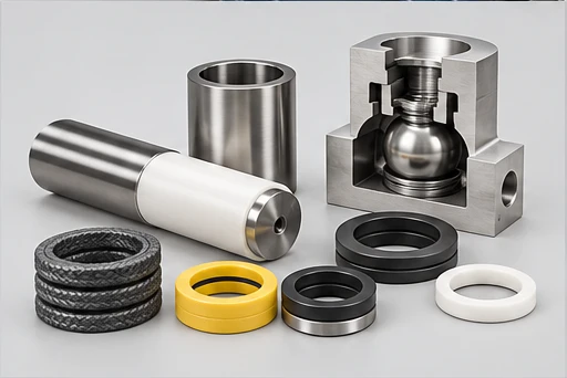
Select pressure and flow at the same operating point. Include the liquid quality, inlet supply, nozzle or process demand and running pattern when reviewing the fluid end, plunger packing and cooling arrangement.
| Wetted components | Fluid end matched to process liquid |
|---|---|
| Sealing | Plunger packing and cooling by duty |
| Liquid / design limits | Confirm liquid composition, temperature, particles and operating conditions |
| Application and liquid | Include this information in the duty review and model selection |
| Required pressure and flow | Include this information in the duty review and model selection |
| Inlet supply | Include this information in the duty review and model selection |
| Operating pattern | Include this information in the duty review and model selection |
| Power supply and package scope | Include this information in the duty review and model selection |
AI-generated family illustrations. The selected configuration follows the agreed model and drawing.
installation

Define inlet pressure, liquid supply, filtration and discharge-pressure controls. Review pulsation and pressure-protection requirements.
Coordinate the driver, transmission, speed, lubrication and cooling with the required pressure, flow and operating cycle.
AI-generated family illustrations. The selected configuration follows the agreed model and drawing.
applications
Actual supplied footage shows a hot-steel descaling line. The pump duty must be reviewed with nozzle flow, line pressure, inlet quality and the operating sequence.
Discuss the operating duty →For industrial cleaning, match nozzle demand, pressure at the point of use, inlet-water quality and the cleaning sequence. Review the liquid end, sealing and drive at the selected pressure-flow duty and operating speed.
For steel descaling, match nozzle demand, pressure at the point of use, inlet-water quality and the cleaning sequence. Review the liquid end, sealing and drive at the selected pressure-flow duty and operating speed.
For pressure testing, define the test medium, test pressure, filling flow, pressure-hold sequence and pressure protection. Review the liquid end, sealing and drive at the selected pressure-flow duty and operating speed.
For water injection, define water quality, inlet supply, injection pressure and flow, filtration and the running cycle. Review the liquid end, sealing and drive at the selected pressure-flow duty and operating speed.
supply scope
Define the pump configuration, installation interfaces, controls and documents in the quotation.

Pump, motor and common base for a compact electric installation. Agree the transmission, guarding and connections for the required duty.

A photographed arrangement with pressure instrumentation and a pulsation vessel. Specify the required instruments and pressure-control equipment.
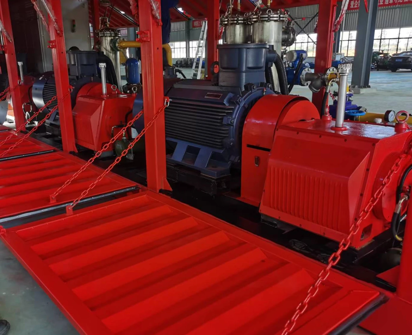
The supplied water-injection photograph illustrates a larger integrated arrangement. Define the pump, drive, piping and auxiliaries for the actual water quality and site.
manufacturing
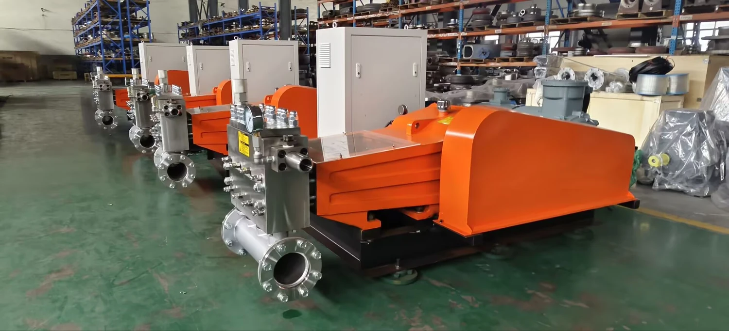
Pump heads, power ends, drives and supporting equipment are brought together in the assembly area. The arrangement and included equipment follow the selected order.
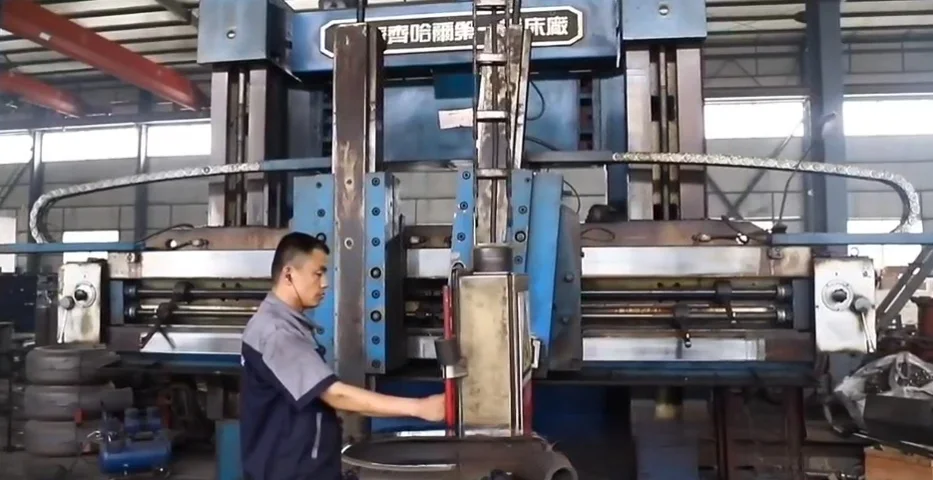
Machining prepares bores, mounting faces and connection interfaces. Drawing revisions, material requirements and agreed inspection points define the work.
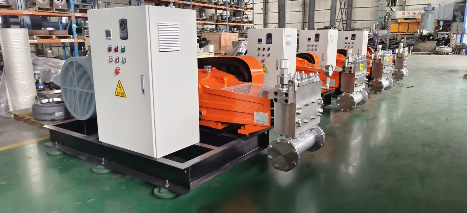
Review the assembled drive, support base, connections and service access against the agreed arrangement before shipment.
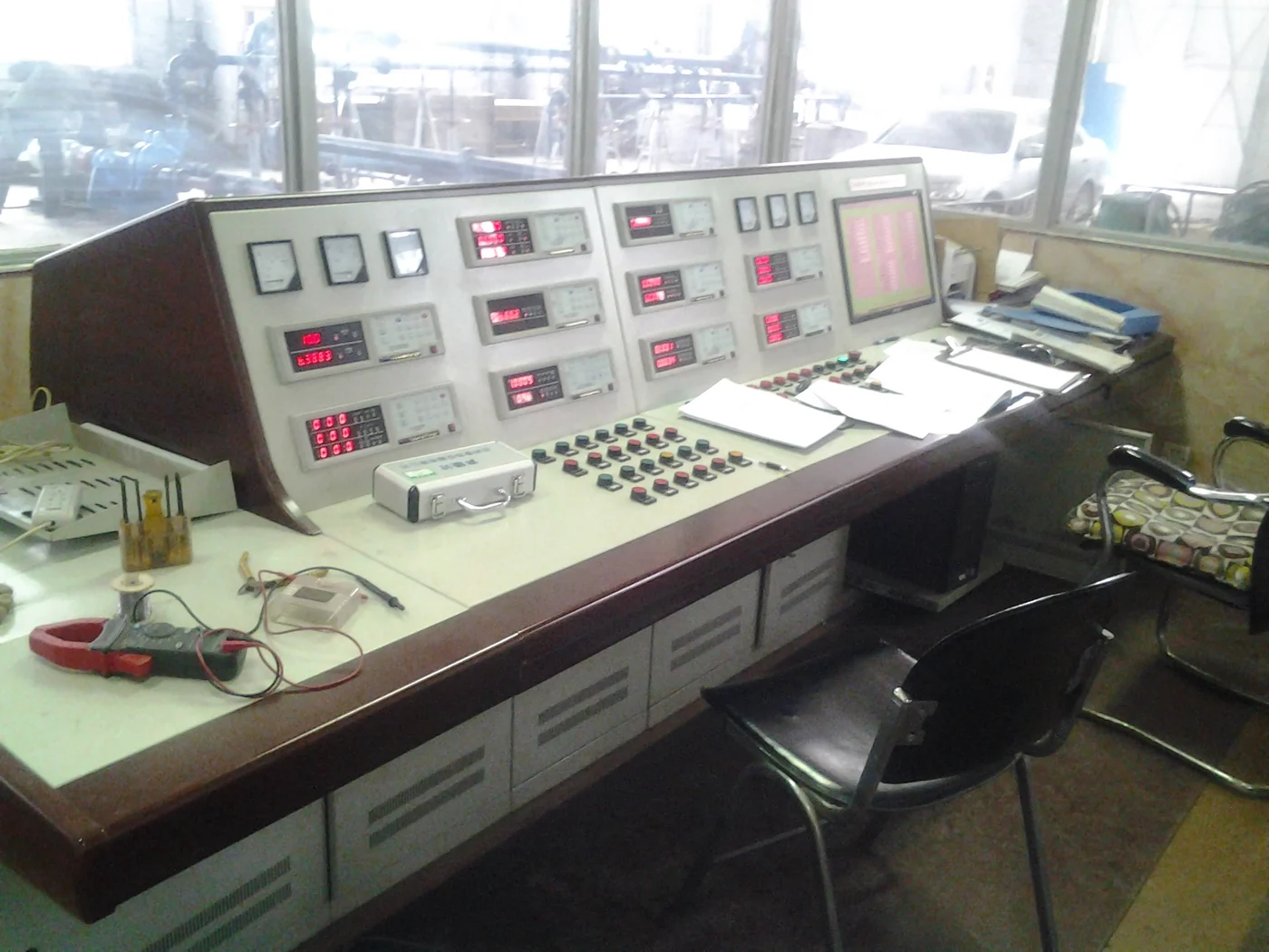
Define the required inspection scope, operating checks and acceptance records for the selected equipment.
documents
Original catalogue / brochure reference. Review the applicable model, version and units.
Open original PDFRequest the selected model curve, arrangement drawing, materials, installation instructions and agreed inspection records.
Request technical documentsquestions
Application and liquid; Required pressure and flow; Inlet supply; Operating pattern; Power supply and package scope. Review the complete duty on the applicable model curve.
Fluid end matched to process liquid. Plunger packing and cooling by duty. Confirm compatibility with the complete liquid composition and temperature.
Catalogue ranges summarize printed records and may combine different conditions. Check each model against its source curve and required speed.
Confirm pump, driver, controls, auxiliaries, spares, drawings, manuals and required test records in the agreed quotation.
enquiry
Describe the liquid, required output and site arrangement so BBP can review the model and equipment scope.